


3(4) 2008
 |
|
 |
ARCHITECTURE AND MODERN INFORMATION TECHNOLOGIES
МЕЖДУНАРОДНЫЙ ЭЛЕКТРОННЫЙ НАУЧНО-ОБРАЗОВАТЕЛЬНЫЙ ЖУРНАЛ ПО НАУЧНО-ТЕХНИЧЕСКИМ И УЧЕБНО-МЕТОДИЧЕСКИМ АСПЕКТАМ СОВРЕМЕННОГО АРХИТЕКТУРНОГО ОБРАЗОВАНИЯ И ПРОЕКТИРОВАНИЯ С ИСПОЛЬЗОВАНИЕМ ВИДЕО И КОМПЬЮТЕРНЫХ ТЕХНОЛОГИЙ
USING RULES IN THE DESIGN PROCESS
ИСПОЛЬЗОВАНИЕ ПРАВИЛ В ПРОЦЕССЕ ПРОЕКТИРОВАНИЯ
Magdalini-Eleni Pantazi (М. Пантази)
Department of Architecture, Massachusetts Institute of Technology, USA
Introduction
The most challenging and enjoyable aspect of architectural design occurs during the early phase of design, when the architect is still free to play with concepts and shapes while exploring different ideas to solve a design problem. During this process, a variety of tools and procedures can be used to actualize architectural objects as possible solutions to the design problem. The goal is to develop a representation that can most accurately illustrate the designer’s thoughts, while at the same time leaving enough space for further investigation and exploration. In Schon’s words “creative fields are characterized by the generation and manufacture of objects for reflection and evaluation.”1 The generation and manufacture of an object, however, is not actualized in the same way in all creative fields. On the contrary, as Robin Evans notes, there exists a “peculiar disadvantage under which architects labor, never working directly with the object of their thought, always working at it through some intervening medium, while painters and sculptors, who might spend some time in preliminary sketches and maquettes, all end up working on the thing itself.”2 Throughout the whole design process, architects model an object that is not yet realized, using different kinds of processes and representations in order to illustrate its form and understand its structure. The object comes to life through the model, and the interaction between model and object leads to a constant exchange of information between the two, until the culmination of the design process in the realization of the object.
In the above context, architectural design can be perceived as a conversation between the designer’s thoughts and the object under construction. This conversation is conducted with the aid of a design medium. Two are the important features that determine the outcome of this conversation: the design process and the object itself. The design process refers to the steps that the designer follows from the initial idea through its exploration to the final result. The object, on the other hand, consists the vehicle for the exploration as it reflects the strategies employed by the designer. The object, in other words, is considered as part of the architectural design process that enhance design development.
The focus of the present paper is on the early phase of the architectural design process: this of exploration and creativity. The scope of the study is to examine the types of actions that architects form around constraints during the creative phase in order to both address a design problem and work towards its solution. In that framework I first pose some questions regarding the strategies that architects employ while designing. I then set up an experiment to examine these questions. Three basic features that characterize the structure of the experiment are then introduced and analyzed: the design problem, the design process and the feedback relationship. Finally, I analyze and discuss the results of the experiment.
The early phase of design describes designer’s actions from the introduction to the design problem, through the exploration of the possible solution alternatives and their transformations to the crystallization of a first satisfying design result. A basic feature of the architectural design process at this stage is its undefined and unclear character: designers seem to proceed in design solutions in a rather ad hoc way3 that makes difficult the establishment of systematic methods of approaching the design problems.
This undefined character of the design process is proved problematic especially today, where the introduction of new design tools in the field of architecture challenge the traditional ways of designing. While traditional tools and processes are based on designer’s intuition and support the use of implicit actions, the new computational tools are based on very explicit processes and rules. Different design tools impose different design processes, so if we want to use, improve or even invent tools to effectively address the design process then we need to have a better insight on how designers form their actions and what patterns of actions they follow during the design process. As a first step to this research the following questions are addressed:
How do designers formulate the information contained within a design problem?
How do designers organize their actions towards a design solution?
How do designers move between different solutions?
Do they use rules or patterns of rules in these processes? And if so, what kind of
rules or patterns of rules do they use?
To answer these questions I need to introduce first the design problem, the design process and the feedback relationship.
Design problem
In his research on computational approaches to architectural synthesis, Kotsopoulos quite rightly selects and uses Newel’s and Simon’s conceptualization of the workings of design questions. According to them “a person is confronted with a problem when he wants something and does not know immediately what series of actions he can perform to get it.”4 Depending on the type of the problem, the path to the solution can be easier or harder. For example, problems that scientists or engineers deal with are definable and may have solutions that are findable. In these problems, usually the mission is clear such as finding the solution to an equation. Furthermore, an exhaustive formulation can be stated containing all the information the problem-solver needs for understanding and solving the problem, provided that he/she knows how to do it.
On the other hand, this is not the case for problems that are ill-defined, ill-structured, or wicked5. On the contrary, these problems have no clarifying traits, neither a single solution. Additionally, the necessary information about the design problem is not, or even cannot be, available to the problem solver. The design problem needs to be structured upon objective and subjective parameters, for example the program for a building and the personal interpretation of the program respectively. An example that best illustrates this situation is that of a design competition. A plethora of totally different design solutions is proposed as an answer to the same program, the same site, the same time-frame and the same client. It is clear, therefore, that architectural design problems cannot be organized deterministically and also that they do not have a unique solution. What do designers tend to do, then, when they seek a solution?
Gross et al. supported that constraints play a significant role in design. They described design as an exploration of constraints and argued that constraints provide a knowledge representation that supports reasoning about designs and designing. In order to test their hypothesis they did not provide any empirical evidence, but they developed computer software, “the constraint manager”, to describe design.
Based on the above considerations, about the characteristics of the design problem and the importance of constraints in designing, I created two design problems. The design problems had the same objective: the creation of a family house in a rectangular site. While the size of the site was the same in both cases, the site changed: in one case it was placed in a city and in the second case in the countryside. The creation of the house in the city had to follow a specific building code and also respond to the urban structure. The creation of the house in the country side, on the other hand, was not bounded on the same constraints. The site was surrounded by nature and the architects were free from strict building codes.
Design process
As mentioned above the design problem is strongly related to the design process. Therefore, the ill-character of the design problem affects the design process, which cannot follow an explicit path to reach the final product and is characterized by the use of implicit rules. This fact is sustained by the solution-focused processes that designers use in contrast to the scientists problem-focused processes. Lawson’s studies on design behavior revealed that the architects learn about the problem by trying out solutions so as to achieve the desired result, whereas the scientists are more concerned on studying and analyzing the problem to discover the rule.
In this framework, throughout the experiment, I investigated if and how architects form and follow rules while designing. I specifically examined the formation of patterns of rules according to different constraint conditions. Furthermore, I explored the methods that architects applied in order to handle the feedback relationship while designing. The term feedback is used to describe the process of reinterpretation of design: the designer observes a new relation on the produced design; he/she evaluates it against the initial idea or hypothesis and then alters the design solution.
Feedback relationship
Several studies based on protocol analysis have acknowledged the importance of reinterpretation in the early phase of design and tried to identify mechanisms and tools that support it. Studies have also examined the role of sketching in reinterpretation as well as discovered the kinds of interactions that architects have with their designs. In a series of papers, Goldschmidt has examined protocols of design involving novice and expert architectural designers. She proposed that the dialectic between arguments of “seeing as” and “seeing that” during the process of sketching “allows the translation of the particulars of form into generic qualities and generic rules into specific appearances”.6 In the same line, Schon and Wiggins suggested that sketching consists a visual representation that can potentially be perceived in different ways through a design process that develops along the schema see-move-see. Goel reversed the question and investigated the properties of sketch that allow for reinterpretation. He acknowledged the importance of “lateral transformations” and supported the hypothesis that because sketching constitutes a symbol system, which is characterized by syntactic and semantic denseness as well as ambiguity, it allows lateral transformations to occur. Symbol systems, however, that are non-dense and unambiguous will hamper the exploration and development of alternative solutions and force early crystallization of design development.
Goel’s conclusion is similar to an observation made by Ivan Sutherland back in 1975. Sutherland comment concerns reinterpretation relatively to the structure of the design in different representational media. He argued that because pencil and paper have no inherent structure, they can be decomposed and manipulated in any manner of interest to the designer. An evolving design may thus have alternative descriptions that may change from time to time in unanticipated ways. The structure of the computer design, on the other hand, presents an obstacle to all of this, because it is fixed in specific design operations.
As discussed above, I conducted an experiment to investigate the design problem, the design process and the feedback relationship through the patterns of actions that architects form around different constraint conditions. In this way, constraints can be considered to be the driving force that organize the architects actions from the formulation of the problem towards the creation of a solution. The types of constraints vary: some are external and relate to the site or to the program, while others are personal or internal and express architects preferences. In most cases the combination of the two leads the architect to outline the solution. Constraints alone, however, are not enough to guide architects to the solution. It is also the various types of actions that architects form around the different types of constraint that lead the exploration and filter the alternative solutions. The way that these actions are organized and the different groups that they form were under examination throughout the experiment.
The experiment
The aim of the experiment was to investigate the use of design rules in response to different design situations. The feature that defined the difference between these situations was the constraint condition: design problems were divided in less constrained versus more constrained ones. The types of rules that architects formed so as to address the different constraint conditions were in the focus of the experiment. The method selected for it was a protocol analysis of reports of subject’s design thoughts. The think-aloud verbal reports method,7 was not employed, because as previous works suggested talking aloud is possible to influence designer’s actions.
The experiment was conducted with the participation of six professional architects who work in the architectural firm Bergmeyer and they are members of the research group Affinities. The experiment consisted of three tasks: two design tasks and one report task. In each design task the participants were asked to solve a design problem in a one-hour session. They were provided with a simple diagram presenting the site in which they were asked to locate a family house. Participants were free to use whatever representational medium they wanted as tool for design. They were not asked to describe their moves and actions while they were designing, nor were they interrupted during that time. In order to keep track of the process that each architect followed towards solving the design problem, a video camera was used to record the architects design decisions.
The two design tasks happened sequentially in two day time. One week after the design tasks were completed the report task followed. I met with each participant and together we reviewed the process he/she followed with the aid of the videotapes. More specifically, while watching the videotapes, I asked each participant to describe the moves and the decisions he/she took during the design process. They were asked to remember and report with as much detail as possible what they were thinking as they were designing. Participants were not interrupted with questions during the report, except when the participant skipped a design event without commenting on it, when I asked him/her to describe it. The whole session was audio taped.
Protocol analysis
The analysis of the protocol followed the subsequent steps. First, the verbal protocol recorded from the design sessions was transcribed. The next step was the analysis of the designs based on the visual representation of the drawings and their verbal descriptions. Every design solution was divided into three segments:
1. The formulation of the design problem and the organization of design actions,
2. The construction of responsive mechanisms, and
3. The final solution.
In the last step the two design solutions that each participant produced in response to the two design problems were compared according to the above three segmentation categories.
The analysis of the design solutions led to the formulation of three groups of design activities, depending on the different ways that the architects responded to the design problems and the various design actions that followed this response: processes based on problem-derived constraints (site and program) and processes based on personal-derived constraints. While the elements involved in the above processes continuously interact and inform one another during the whole period of the design process, the focus of the analysis was to discern a dominant element that structured the process towards the design solution.
The aim of the present study was not only to identify possible types of rules that architects employ at the early phase of design, but also to examine how a computational method can describe these design processes. For this purpose I analyzed the examples with the aid of the computational method of shape calculation8. In this paper I will present one example of the problem-derived constraints category. The example will be developed in four sections:
1 and 2 - Presentation of the first and second design experiment based on the protocol analysis segmentation; 3 - Presentation of the general rule schemas used in the design process, from organization of the design problem to the creation of the final solution; 4 - Illustration of the design process and solution through the model language of shape calculation.
Design problem 01: Formulation of the problem and organization of design actions
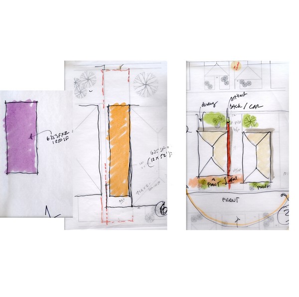
The first action of architect A was to divide the total square footage of the programmatic requirements into two equal parts of 625 sf. He then continued by examining the possible shapes of these parts; both x and y dimensions varied. The house’s x dimension was either the same as the x dimension of the site or was the 3/4 of the site’s x dimension. This reduction provided sufficient space for an exterior sidewalk. The y dimension varied, but was always determined and limited between the boundaries of the neighboring buildings. As a result, two solutions were produced: in the first one the x dimension of the house was identical with that of the site and the house was aligned with the southern (lower) border of the neighboring building. In the second solution a corridor was left on the west side and the house was aligned with the northern boundary of the neighboring building (Fig. 1).
 |
|
Fig. 1. Architect D, Design problem 01: Organization |
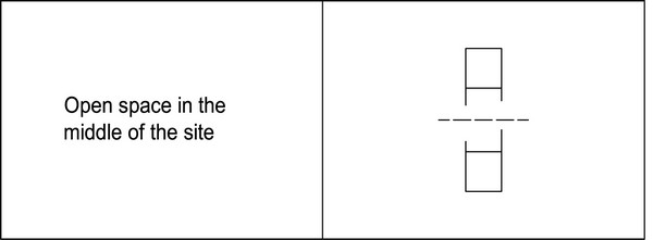
On the next tracing paper the architect started tracing the lines of the general site plan: the neighboring buildings, the set-backs, the solar orientation. In this sketch he defined the back and front sides of the house and then placed the accesses to it: one on the back and the second one in the middle of the site, coming from the front. His next move was to place the house uses; kitchen at the back, living room at the front and, accordingly on the above floor, two bedrooms at the back and master bedroom at the front. His final decision on this sketch was to place the parking space at the back.
The completion of this sketch helped the designer to form a decision concerning the way he was going to proceed with the design solution. His response (Fig. 2) to the site constraints was to create a house with a garden somewhere in the middle.
 |
|
Fig. 2. Architect D, Design problem 01: Response |
Actual design
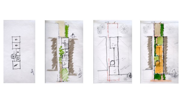
In the next sketch he proceeded with a diagrammatic arrangement of spaces on the footprint of the second solution, the one with the pathway. The general orthogonal footprint of the house was divided into two parts, which were to accommodate the basic functions of the house: one (part A) was located at the front of the site and the second (part B) at the back. The two parts were connected with a third shape (part C) which had to fit the size of the other two parts (in the x dimension) and hosted the house’s internal circulation as well as the secondary functions. The architect was using a rational way of dividing space, by always selecting a specific proportion to work with. The length of the house was not yet determined. The architect’s last action in this sketch, which formed the final version of the house schema, was to locate a circular stair (part D) in the North-West corner of the front part.
Moving to the next sketch, the architect started dimensioning the house’s spaces in order to determine the final shape of the house. He resized the house; part A and B were aligned with the east neighboring house. Consequently, part C became longer in order to cover the distance between the other two parts. The x dimension of part A changed and became the same as the x dimension of the site. Parts B and D remained unaltered. Another change in this sketch was the relocation of the garden entrance from the front to the back (Fig. 3).
 |
|
Fig. 3. Architect D, Design problem 01: Design |
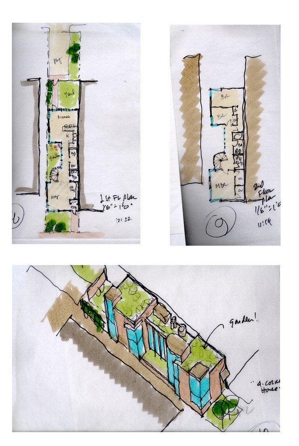
In the following sketch the architect continued to resize the house’s dimensions. Part C became shorter, because the previous solution exceeded the required square footage. Part D was also changed and became tangent to part A. At this point the designer identified as an important element of his design the four corners of the building, which he then highlighted by placing there corner windows. After this action he named his house “the corner house”.
In the design of his final solution (Fig. 4) the last resizing action occurred; part B became the same as part A. The architect then proceeded by refining both floors of his design solution. In his last sketch he designed an axonometric so as to display different aspects of his solution as shown on the facades of the house.
 |
|
Fig. 4. Architect D, Design problem 01: Solution |
Rules in the design process
The architect proceeded in the designing by first identifying the site’s special conditions and constraints in order to find the basic guidelines to develop his design solution. This process resulted in the formation of his response to the design problem, the decision to create a house with an open space in the middle.
The actualization of this design decision on paper was characterized by the use of a symmetry rule. The shape of the house was abstractly divided into two parts and whatever was happening on the one side was affecting the other side, either in terms of distinguishing or mimicking. The architect was using bilateral symmetry. Another rule employed in the design was that of connection between two parts. The architect created two basic spaces, which he decided to connect with a smaller, secondary third space. An interesting action of the architect was to place the circulation in a corner of the house. The stairs took the shape of a circle, just from the beginning of the design process, and were located at the North-West side of the house. Lastly, the architect’s actions to rationally divide the spaces of the house constitute another rule applied in the design solution. The architect’s division moves were always guided by a proportional relationship: the connection shape is divided in two equal parts, the initial part of the house hosting the two bedrooms is again divided in two, while the room corridor constitutes one-fifth of the bedroom’s dimension.
Overall, the architect at the beginning of the design activity forms a general framework based on the manipulation of certain site constraints. These frameworks involve some general laws that provide the architect with a method of approaching the design problem. As the architect proceeds with the solution, these general laws are gradually made more specific and refined explicit design actions.
Design problem 02: Formulation of the problem and organization of design actions
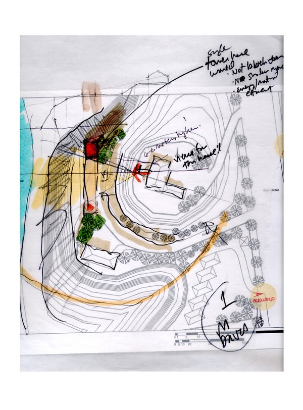
In the second design problem the architect started by immediately tracing the lines of the general site plan. Again, he was interested in the solar orientation, the neighboring buildings, the possible accesses to the house, but also in the views to the sea and the site’s slopes. First the information extracted from the site did not provide him with a specific guideline that he could use to start working with. Since he was stuck, he then decided to create a sketch of a section in order to examine the slopes of the site in more detail. That sketch helped him realize that the neighbors’ views constituted an important characteristic of the site he should take into consideration: he decided their ocean shouldn’t be blocked. This thought formed his response to the problem’s constraints and he opted to locate two structures at the ends of the site. While still drawing on the same sheet, the architect went back to the plan and started developing his idea further (Fig. 5).
 |
|
Fig. 5. Architect D, Design problem 02: Organization |
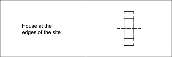
First he placed an axis of symmetry on the site and then he continued by designing two symmetrical lines at an angle to indicate the neighbors’ views. He knew by that time that he wanted the house located at the two edges of the site. These two last lines gave him two quadrilateral shapes the edges of the site. The architect liked this result and so he decided to incorporate it in his solution; he used the north quadrilateral to put the house, and the South one to locate the garage (Fig. 6).
 |
|
Fig. 6. Architect D, Design problem 02: Response |
Actual Design
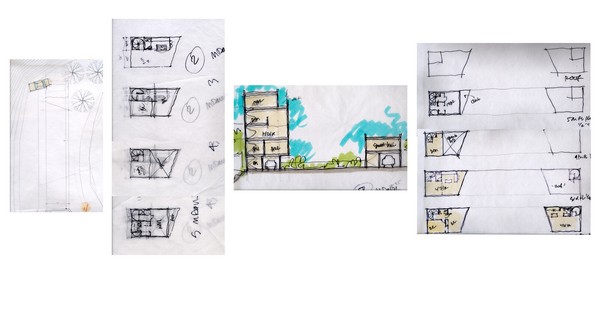
The architect proceeded in a new tracing paper. He changed scale – moved to a larger one – and created several plan variations. In every plan sketch the stairs were placed in the same location, in a 90 degree corner. For dividing space into smaller rooms the architect followed a rational system of proportions of halves or thirds. The quadrilateral shape of the house did not affect these divisions, because the architect had extracted a rectangular shape out of it and was proceeding with that. The remaining triangle shape used either as a deck or as a room expansion (Fig. 7).
 |
|
Figure 7: Architect D, Design problem 02: Design |
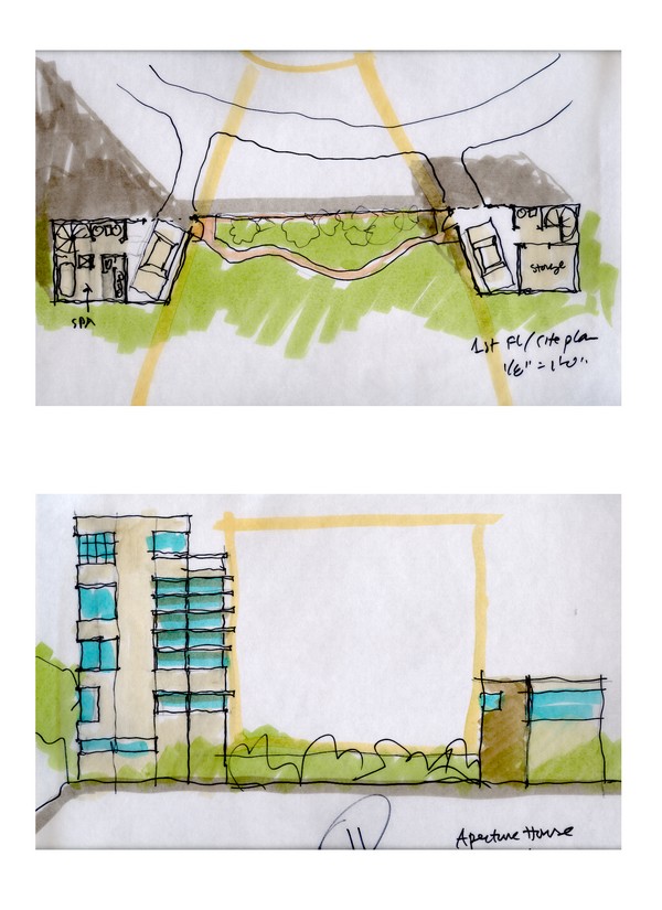
After having finished with the plans the architect proceeded in section. From the first sketch until this point the architect had taken a decision to create a guest house above the garage space. The architect used the last sketches (Fig. 8) to illustrate more accurately his idea. He designed the final plans of each floor, then a west elevation and finally the first floor plan in the general landscape.
 |
|
Fig. 8. Architect D, Design problem 02: Solution |
Rules in the design process
In the second design problem the architect, once more, proceeded by first identifying the site’s special conditions and constraints in order to find a similar guideline to help him develop his design solution. This process resulted in the formation of his response to the design problem described by the design decision of creating a house at the edges of the site.
Further exploration of the above design idea resulted in an emergent shape; that of quadrilateral. The architect employed the identity rule (Stiny, 2006) that describes the situation were the architect recognizes a shape in the drawing that she could not see before, extracts it from the surroundings, incorporates it and proceeds with the solution – this rule will be further analyzed in a following section.
Even in this situation of emergence, the architect employed the rule of bilateral symmetry, as in the previous design problem. The house was divided into two parts and whatever was happening on the one side was affecting the other side, either in terms of distinguishing or mimicking. The difference in this case was that the symmetry was followed only in plan and not in elevation or in section. Another rule employed in the design, similar with one employed in the previous solution, was that of connection between two parts. In this case the architect designed the connection only in the last drawing using a curvy shape. He said “at the beginning I thought of connecting them (the two houses) with a straight stripe kind of way, but then I changed my mind and I followed the landscape”. A different rule, used in the same way in both design solutions, describes the location of the circulation, which is always placed in a corner of the house. The architect was treating the stairs not as a structural element of the house, but rather as something that he wanted to hide. His wish was for the stairs to occupy the minimum possible space, “I placed the stairs there for efficiency reasons.” Finally, the architect’s actions of rationally dividing the spaces of the house describes another rule applied in the design solution, same as before. The architect’s division actions were always guided by a proportional relationship of halves and thirds.
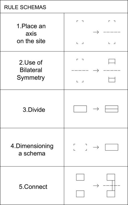
Rule schemas
The protocol analysis revealed that the architect proceeded in a similar way in both design problems. In the two cases the architect developed his response to the design problem by forming his actions around constraints deriving from the special site conditions. The comparison between the design activities of the architect, in both cases, revealed that some of these actions were similar in the two processes. These actions can be described by rules, which for the present thesis comply with the language of a shape grammar formalism. At the early phase of design, the rules that the architect used were not fixed or explicit, but were rather expressing some general intentions about spatial relationships. They could apply to any spatial configuration and for that reason they do not require a specific vocabulary of shapes. Therefore, for this stage of design, rule schemas are proposed instead of specific rules and are expressed in the following table (Fig. 9). These general rule schemas describe the architects design process, as well as the final design solution.
 |
|
|
a) |
b) |
|
Fig. 9(a,b). Architect D, rule schemas | |
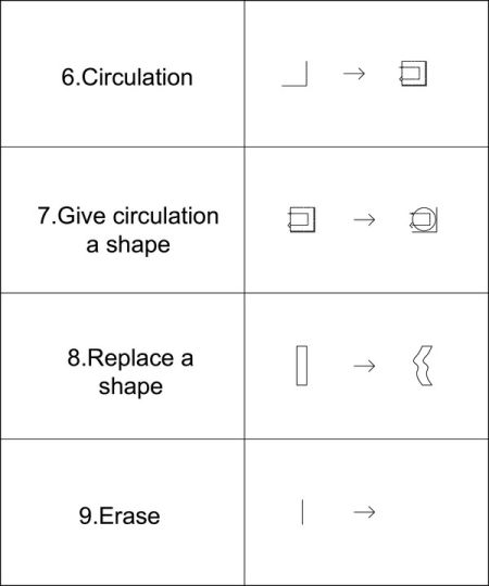
Rule schemas’ descriptions
In the following section each rule schema will be described and analyzed separately.
Rule schemas 1 and 2: The first two rule schemas refer to the action of symmetrically designing space and more specifically to the application of bilateral symmetry. As William Mitchell states in his book The Logic of Architecture (Mitchell, 1989), bilateral symmetry is the kind of symmetry possessed by the human body. Claude Perrault described symmetry as “the relationship which parts on the left side have with those on the right, those high up with those low down, those in back with those in front” (Mitchell, 1989). Therefore, the symmetry operation can be described by a reflection across an axis. In order to accomplish the above operation, one should start by placing an axis of symmetry into the site, an action that is illustrated in the first rule schema (Fig. 10).
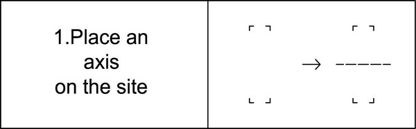 |
|
Fig. 10. Rule schema 1 |
The next step is the actual application of the rule of bilateral symmetry, as it is formalized in the second rule schema. This rule describes the characteristic of the architect’s design compositions to evolve through isometric transformations (translations, rotations, reflections, and compositions of these) (Fig. 11).
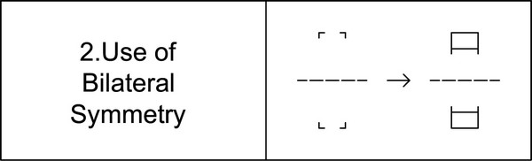 |
|
Fig. 11. Rule schema 2 |
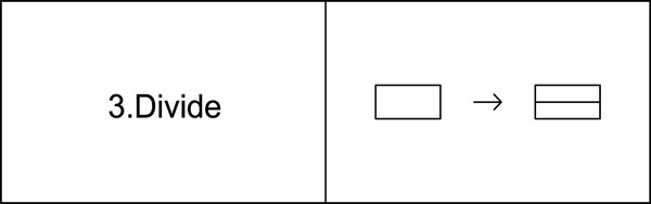
Rule schema 3: This rule schema allows the division of an initial shape into several parts. The division should always occur in a ninety degree relationship with the initial shape’s sides (Fig. 12).
 |
|
Fig. 12. Rule schema 3 |
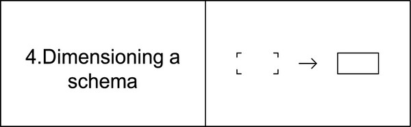
Rule schema 4: The fourth rule schema describes the action of adjusting an initial diagrammatic schema so as to meet the exact programmatic requirements. An initial vague shape could be dimensioned and consequently transformed into different shapes until it is finalized to the one fulfilling both the architect’s intentions and the program specifications (Fig. 13).
 |
|
Fig. 13. Rule schema 4 |
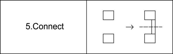
Rule schema 5: The fifth rule schema permits the connection between two shapes through the use of a third shape. In the rule illustration two quadrilateral spaces are connected with a third quadrilateral shape. The quadrilateral shapes do not serve as the actual representation of the shape, but rather indicate a general shape configuration (Fig. 14).
 |
|
Fig. 14. Rule schema 5 |
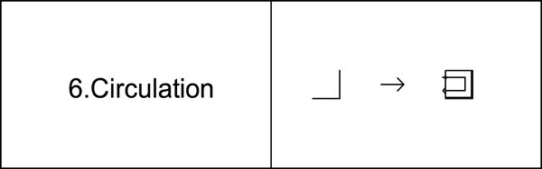
Rule Schema 6: This rule schema describes the location of the house circulation between the different floors in a corner of the house. Given a house corner, the rule illustrates the starting point of the circulation as well as the end point within the boundaries of the shape (Figure 15).
 |
|
Fig. 15. Rule schema 6 |
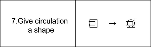
Rule schema 7: The seventh rule schema provides a shape to the schematic representation of the circulation. The shape does not have a specific from and always depends on each design problem’s special conditions. For example in the experiment’s two design conditions the architect chose to work with a circular shape. In a different problem, however, he could proceed with a totally different shape (e.g. rectangular, square etc.) (Fig. 16).
 |
|
Fig. 16. Rule schema 7 |
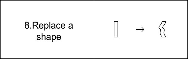
Rule schema 8: This rule schema allows the replacement of a shape with another one of different kind (Fig. 17).
 |
|
Fig. 17. Rule schema 8 |
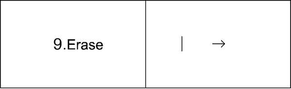
Rule schema 9: The last rule schema permits the action of erase. During the design process the architect can select a line or several lines that he does not want and erase them (Fig. 18).
 |
|
Fig. 18. Rule schema 9 |
Schematic derivations
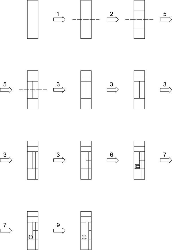
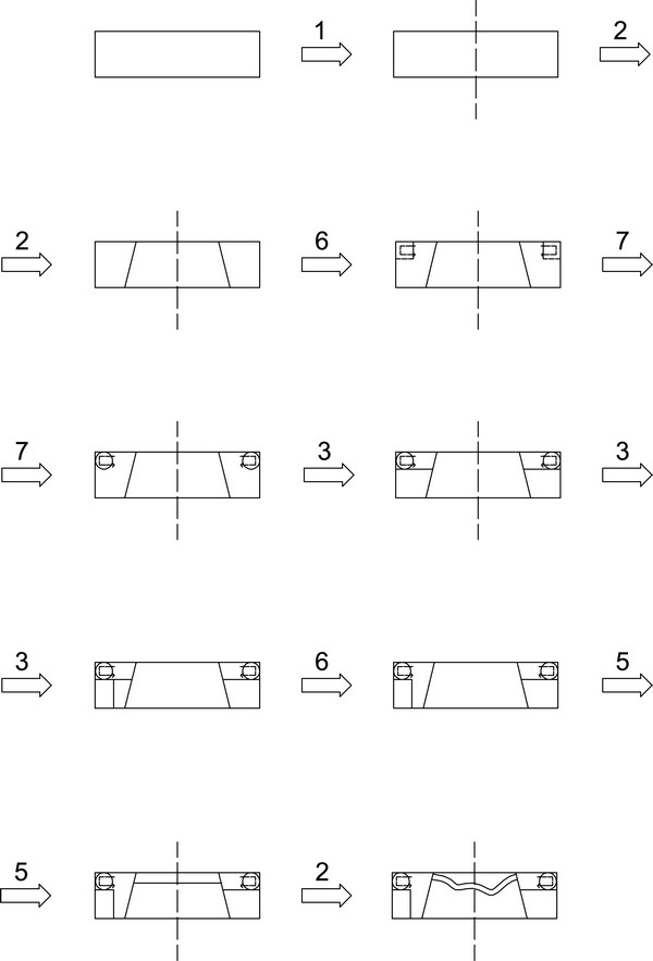
The rule schemas described in the previous section are put into use in each design process. They serve as guidelines for the architect in order to create plan descriptions. In this section two examples, one for each design problem, will be presented illustrating how the spatial relationships described in the previous tables of rule schemas result in specific plan descriptions. The architect in every design step of each design solution was gradually transforming these general rule schemas to specific and explicit application of rules; a process that resulted in the final solution (Fig. 19, Fig. 20).
 |
|
Fig. 19. Schematic derivation for the first design solution |
 |
|
Fig. 20. Schematic derivation for the second design solution |
Conclusions
In the example presented, the architect formulated his response to the design problems by creating a framework based on the design problem’s constraints. In the first case the architect’s response was the creation of a house with an open space in the middle, an idea that derived after studying the parameters of the site. Apart from the general set of rules that the architect developed around the constraints in the form of a response to the design problem, other sets of rules were also created that referred to his personal design methods. Once more these sets of rules provided a design framework by describing spatial relationships in a general manner and could thus be represented by Rule Schemas.
For example, an important rule schema was that of the use of bilateral symmetry. The combination of these two sets of rules provided the guidelines towards the design solution. It appeared that the constraints served as an impetus for the architect to impose his personal design method. This fact does not mean that the rule schemas corresponding to the design problem’s constraints were abandoned, but rather that they were incorporated in the personal design method of the architect. In other words, the architect created frameworks that provided general methods of approaching the design problem and could be described by Rule Schemas. A basic characteristic of these rule schemas is that they create qualitative descriptions of the objects under construction. This means that during the design process the object is not defined by explicit rules and norms, but rather with a schema that describes its general aspects. The benefit of this feature is that it leaves space for an idea to evolve and to become something new and different, rather than locking an idea to specific expressions. It provides a way of thinking on something, rather than providing a definite solution for it. In that sense, qualitative descriptions allow for different interpretations. For example, bilateral symmetry could be applied in almost every situation that describes a reflection across an axis, from a human body to a classical architectural plan, without defining the exact way of its application, but just providing a guideline to work with.
In conclusion, the analyzed example prove that the architect used rules during the early design phase. The characteristic of these rules, as stated previously, is that they gradually move from a schematic description to a specific one. The developed shape grammar managed to capture this transformation from general to specific by rule schemas that convert gradually to specific rule via their application in design. Furthermore, the shape computation shown offered a formal way of describing design composition from scratch without imposing any specific design procedure, but rather by adjusting to the special design process of the architect.
Bibliography
Cross, Nigel. Designerly Ways of Knowing. London: Springer, 2006.
Goel, Vinod. Sketches of Thought. Cambridge, Mass. : MIT Press, 1995.
Goldsmichidt, Gabriela. “The dialectics of sketching.” Creativity Research Journal vol.4 no 2 (1991): 123-143.
Goldsmichidt, Gabriela. “On visual design thinking: the vis kids of architecture.” Design Studies vol.15 no 2 (1994): 158-174.
Gross, Mark, Ervis, Stephen, Anderson, James and Fleisher Anderson. Constraints: Knowledge representation in design. Design Studies vol. 9 no 3(1988); 133-142.
Kotsopoulos, Sotirios, Constructing Design Concepts: A Computational Approach to the Synthesis of Architectural Form, Cambridge MA: PhD Dissertation MIT, 2005.
Lawson, Bryan. How designers think, Oxford: Elsevier/Architectural Press, 2006.
Mitchell, William. The logic of architecture: Design, Computation and Cognition, MIT Press, Cambridge, 1989.
Newell, Allen and Simon, Herbert. Human Problem Solving. Prentice Hall, 1972.
Rittel, Horst and Webber, Melvin. “Dilemmas in a general theory of planning.” Policy Sciences vol.4(1973): 155–169.
Robin, Evans. Translations from Drawing to Building. London: Architectural Association Publication, 1997.
Schon, Donald and Wiggins, Glen. “Kinds of Seeing and their function in Design.” Design Studies vol.13 (1992): 135-156.
Simon, Herbert and Ericsson, K. Protocol analysis: verbal reports as data. MIT Press: Cambridge, 1993.
Stiny, George. Shapes, MIT Press, Cambridge, MA, USA, 2006.
Sutherland, Ivan. “Structure in Drawings and the Hidden-Surface Problem.” In Reflections on Computer Aids to Design and Architecture, edited by Negroponte N., New York: Petrocelli/Charter, 1975.
Foot-notes
Donald Schon, Educating the Reflective Practitioner (New York, NY: Jossey-Bass, 1990).
2 Evans Robin, Translations from Drawing to Building, (London: Architectural Association Publication, 1997).
3 Nigel Cross, Designerly Ways of Knowing, (London: Springer, 2006).
4 Kotsopoulos Sotirios, Constructing Design Concepts: A Computational Approach to the Synthesis of Architectural Form (Cambridge, MA: PhD Dissertation MIT, 2005): 20.
5 Horst Rittel and Melvin Webber, “Dilemmas in a general theory of planning,” Policy Sciences vol.4(1973): 160.
6 Gabriela Goldsmichidt, “The dialectics of sketching,” Creativity Research Journal vol.4 no 2 (1991): 128.
7 Herbert Simon and Anders Ericsson, Protocol analysis: verbal reports as data, (MIT Press: Cambridge, 1993).
8 Stiny, George. Shapes, MIT Press, Cambridge, MA, USA, 2006.
