


2(3) 2008
 |
|
 |
ARCHITECTURE AND MODERN INFORMATION TECHNOLOGIES
МЕЖДУНАРОДНЫЙ ЭЛЕКТРОННЫЙ НАУЧНО-ОБРАЗОВАТЕЛЬНЫЙ ЖУРНАЛ ПО НАУЧНО-ТЕХНИЧЕСКИМ И УЧЕБНО-МЕТОДИЧЕСКИМ АСПЕКТАМ СОВРЕМЕННОГО АРХИТЕКТУРНОГО ОБРАЗОВАНИЯ И ПРОЕКТИРОВАНИЯ С ИСПОЛЬЗОВАНИЕМ ВИДЕО И КОМПЬЮТЕРНЫХ ТЕХНОЛОГИЙ
SIMUIATING DYNAMIC FORCES IN DESIGN WITH SPECIAL EFFECTS TOOLS
МОДЕЛИРОВАНИЕ ДИНАМИЧЕСКИХ СИЛ В ПРОЕКТЕ ПРИ ПОМОЩИ ИНСТРУМЕНТОВ СПЕЦИАЛЬНЫХ ЭФФЕКТОВ
Earl Mark
School of Architecture, University of Virginia, Charlottesville, VA USA
http://faculty.virginia.edu/Mark/
The Studio Method and Setting
Using special effects tools to simulate complex phenomenon in architectural design is a double-edged sword. Powerful special effects tools can describe transformations of geometry and objects in ways that would be difficult to fully reproduce by hand. However, rather than entrusting a quick simulation to catch all potential conflicts or work out all construction issues, the primary advantage is in laying open a larger field of quick investigations. Special effects provides for a preliminary set of comparative studies of spatial, mechanical and formal aesthetic issues. For example, as suggested by a recent paper on the façade of Gaudi’s Sagrada Familia, animations of geometry setup the basis for more in-depth finite element modeling studies later on leading to a more complete study of a recently restored part of the temple. (Bury 04). Once the initial set of design alternatives has been generated, however, a more complete process of physical modeling becomes the means by which to fully test for conflicts, constraints, and desired physical conditions and to narrow down the set of choices. The design process moves between more open ended visualization at the beginning and more constrained physical modeling later on. This process is then repeated as a means of converging upon a better researched set of final alternatives.
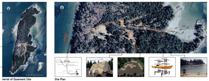
The studio serving as the basis for this study focused on the development of Hungry Island, a 150 acre island at the top of Muscongus Bay in the mid-coast area of Maine. The island is owned by an environmental education wilderness foundation. It is to include two 750 sq. ft. cabins and tent platforms and facilities, as well as a small waterfront with docks and a boat ramp that needed to fit conservation easements. If a naval architect can design a seaworthy sailboat with structural integrity using tension membrane fabrics (sail cloth) that sits lightly upon the ocean, perhaps an architect can design a light-weight ocean front structure that has a small and less heavy ecological footprint. The program for the island involved seasonal wilderness-based activities, including extensive canoeing, kayaking, and sailing. In addition, there was a need to create some sort of special area on a nearby peninsula -- the home campus -- from which these "expeditioning" activities could head out. Crews of young women, lead by craftswomen, would build out whatever is designed, thus creating their camp(s) from the ground up. This architectural scenario setup an opportunity to explore the movement and portability of tension membrane fabrics, consider wind conditions, and ocean tides, and to create a light-weight and transformable architecture with minimal environmental impact.
 | |
|
Fig. 1. Hungry Island, student site plan, Whittecar |
Moving from Sketch to Physical Modeling and Analysis
Not untypical of a final year architectural education, the design studio provided the setting for a detailed investigation into building components. The students began with the construction of simple tension membrane fabric models that were soon translated into animated computer models, assisted in part through three-dimensional scanning. The computer models then were enhanced to consider a greater number of shapes and their mechanical movements. These models were in turn converted by rapid prototyping and other CNC techniques (mostly laser cutting) into more detailed physical models.
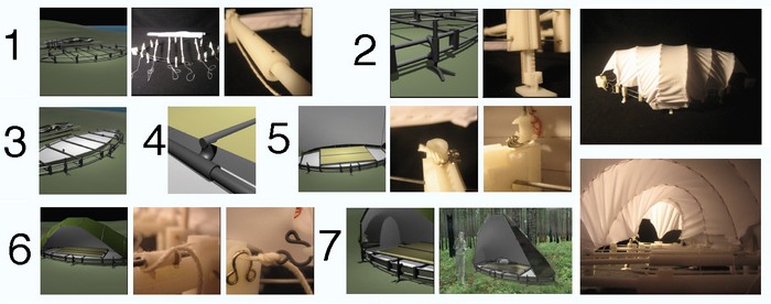
For example, the opening up of a tension membrane roof structure goes through a sequence of changes from a state of being retracted in a small protective storage space in the winter to a state of being unfurled in a larger space during the camping season. At the beginning of the design process, the primitive physical model was developed by sewing cloth onto simple frames where more immediate problems in fabrication and movement could to be detected, and, sometimes more detailed design concerns, such as the inter-operability of tent components or the connections between them also first become apparent.
When converted to a computer model, special effects tools were used to simulate the movement of components and their behavior under conditions of wind and gravity in a way that is analogous to sketching on paper. In this stage, the model is not yet bounded by a full set of physical constraints or subject to realistic calculations of performance such as might be true of a more completely analyzed model. The tension membrane fabric’s movement, stiffness, support structure constraints, and the geometrical transformations possible were modeled with either a NURBS or polygonal simulated fabric. The computer simulated fabric was then studied as it transformed as a tent structure from a storage state to an in-use state. That is, it transformed from being retracted to being unfurled. An armature controls its movement and has limited degrees of freedom. Fabric movement is determined by attachment points to the supporting armature.
In developing the design for the tension membrane fabric, it is necessary to ensure that the armature in motion doesn’t create a puncture or physically interfere with other architectural elements. The armature is animated with the specification of some additional forces influencing the fabric, such as gravity and stiffness. The process of retracting or unfurling is thus visualized as a sequence of animated steps, each one operating under conditions of wind, necessary clearances, and partially studied tolerances of the materials.
 | |
|
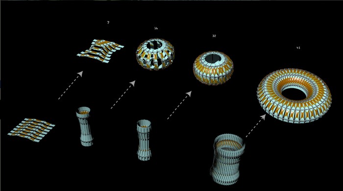
Fig. 2. Unfolding tension membrane fabric of varied numbers of components, Byron |
In the illustration above, after building a preliminary physical model, a student built a parallel skeletal structure with Maya three-dimensional modeling and animation software. Inverse kinematics techniques used in character animation were adapted to setup the movement of the skeleton. The tension membrane fabric was represented with special effects cloth attached to the skeleton framework. The cloth was geometrically constrained at the joints that were located along the segments of the skeletal framework. The tent structure was then rigged (a common term used in both sailing and animation) to unfold into an expanded shape from a more compact form. The cloth surface geometry was subject to gravity and wind, and its movement controlled through its points of attachment to the supporting skeletal structure. The complex movements were thus simulated to explore how the tent fabric transformed, and to study the degrees of freedom needed in the joints of the skeletal frame to facilitate the opening shapes. Carefully specified constraints governed the degrees of freedom of individual joints.
 | |
|
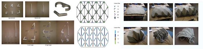
Fig. 3. Finite Element Mesh model on left and rapid prototype of components on right, Byron |
Once the general movement of the fabric had been studied, a module that is replicated to form the initial structure was further analyzed in greater detail. The more detailed module served as a stand-in for studying the whole assembled structure. A finite element mesh surface relaxation program was used to simulate how the fabric would move on the module (see acknowledgement, David Rutten). This program uses a “force density method” over a finite element mesh. It offered more insight into the movement of the fabric, even though in practice it only begins to address the actual composition of materials and their properties.
The finite element mesh study led to a better selection of options for the construction of moveable parts. These parts were investigated within yet a more detailed physical model. The physical model was assembled from rapid prototyping and laser cutting a kit of parts. Investigations of the physical model indicated how the movement of the structure was limited by the size of framing components used in the fabric’s armature. The physical model also revealed conflicts in space that occurred between the components when they moved. This then resulted in greater clarity in the construction of the final design proposal.
 | |
|
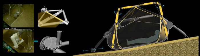
Fig. 4. Model constructed through rapid prototyping as continuing basis for further testing,Bryon |
The final design proposal for both a single tent structure (figure 4) and its incorporation into the roof of a cabin (not shown) resulted from the accumulated set of studies. The initial physical model had been translated to a computer model and then to a more detailed physical prototype. During the design process, the prototype was translated to yet a new computer model for further development. The process of going between physical prototype and digital model was repeated a number of times. The level of effort needed to introduce many ideas in the first computer phase was relatively low. With the use of special effects technology, the complexity of what could be initially envisioned was high. The real complexity implied by the design, however, required further downstream validation in the form of a carefully constructed physical model and prototyping of physical components.
Additional Studies of Animated Cloth and Physical Models
A similar process of physical and computer modeling was undertaken in other student work leading to the rapid prototyping of physical components, testing and evaluation. These structures each had distinct surface geometries and framing systems that facilitated the transformation from a retracted to unfurled state. As was true for the dozen projects in the studio, the design process resulted in both individual tent stand-alone units and their incorporation into a larger cabin structure.
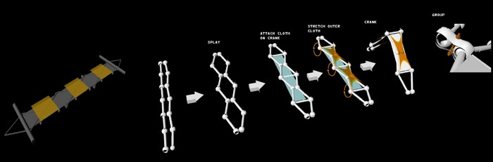
The types of movement varied significantly. For example, in one case, sailboat technology was more directly incorporated into a computer animated study of assembling a tent structure as depicted in figure 5. Methods of rigging sails, cleats used to hold rigging lines, and block and tackle components were developed. The geometry and movement were generated through macro programming by using Maya’s MEL scripting language. Rapid prototyping, laser cutting and sewing components were later used to assemble a series of physical models. Some of the mechanical components emerged from the rapid prototyping machine fully assembled.
 | |
|
Fig. 5. Computer model to rapid prototype was printed and assembled in this sequence, Knowles |
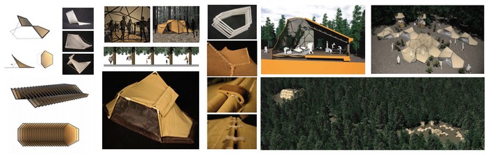
A strategy of unfolding in another project was based on the animated study of surface shapes that could be hinged together in a variety of ways. The cellular-like surfaces resembled “Pringle Potato Chips” according to the student’s self-analysis, neatly stacking for portability.
 | |
|
Fig. 6. “Pringle” scheme depicted in computer model form, prototyped, and rendered, Whittecar |
In a still different approach, a student developed a tent form according to constraints that permitted it to be assembled flat on the ground and then transformed into a doubly curved roof structure with triangulated framing components. The design of the joints, their degrees of freedom and the stiffness of the fabric were significant in the making of the tent form. The student adapted insights gained from a computer animation of a tension membrane fabric transforming from its pre-assembled flat layout to fully assembled form. Degrees of freedom in each joint were mechanically tested at prototypes of increasing scale up to full scale.
 | |
|
Fig. 7. More complex joint design allowed assembly from flattened form, Cheng |
An alternative method of flattening the tension membrane fabric into portable pre-assembled form was initiated through studies of origami shapes. Each alternative was tested for movement of the structure and fabric virtually, and then developed through a combination of rapid prototyping, laser cutting of fabric, and carefully worked stitching of components. The left of figure 8 depicts the computer animated model. The upper right shows the pre-assembly and packing of the tent. The lower right depicts its unpacking from a yellow storage container in a camp site assembly sequence.
 | |
|
Fig. 8. Movements derived from the animated study of origami and resulting design, Sprague |
Wind Tunnel Testing and Analysis
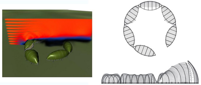
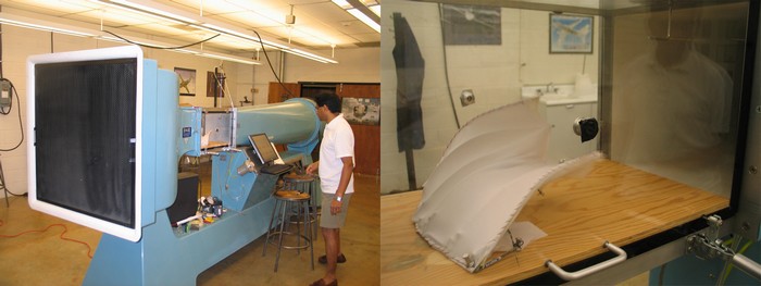
Given that the precedent of sailing helped to inform the prototyping of projects in the design studio, a number of students used wind tunnel analysis fluid dynamics effects software for initial study of the tent forms. The simulations were followed by more complete testing inside a physical wind tunnel. The computer simulations were very speculative and didn’t consider information about fabric tension, loads on structures and other aspects of what would have been needed in a more complete analysis. Still, the virtual wind tunnel analysis suggested how the air might move relative to the tent shapes and where the “lee” conditions were. Subsequently, the deflections of the structures in the actual wind tunnel at speeds of up to 50 miles per hour winds gave some indication of their performance.
 | |
|
Fig. 9. Virtual wind tunnel through the use of fluid dynamics effects, fig 9, Knowles |
 | |
|
Fig. 10. Physical wind tunnel testing and deflection (shown at 50 mph), after model by Knowles |
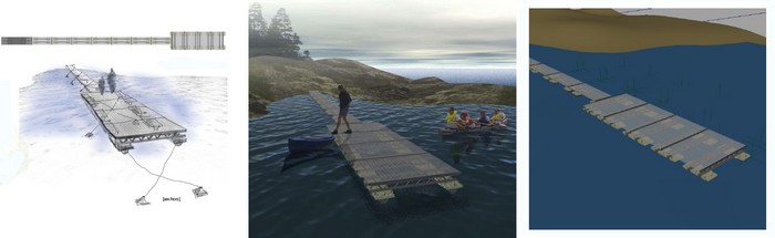
A further application of fluid dynamics effects was to study movement in floating dock structures by creating a special effects ocean. This led to some initial concepts about the relative movement that needed to be accommodated in the dock structure to accommodate high and low tides, if not a more complete analysis of the forces due to water currents. An actual water tank study was anticipated but not realized due to the time constraints of the studio.
 | |
|
Fig. 11. Floating dock simulation using fluid dynamics effects, Cheng |
Conclusion
As design moves increasingly from paper documentation to computer mediated direct fabrication of architectural projects, greater opportunity exists to associate visual representations on a computer with more dynamic and physical modeling methods. The initial development of a project may involve a wide search of design schemes that seem plausible when simulated with special effects tools. This technology doesn’t catch, however, the full range of specific problems of construction, degrees of movement and interference checking realized in rapid prototyping. Accordingly, the design investigation moves from a convincing visual illustration that may look real, as in a special effects movie, to one that engages more demanding conditions of physical construction. The geometrical computer model moves directly to physical fabrication through rapid prototyping and CNC processing. Analysis can proceed in parallel way from exploring the design with special effects tools to real physical testing in simulated conditions (e.g., a wind tunnel).
The promise of this approach is not to avoid the need for expertise in fluid dynamics for more meticulous testing of wind loads or finite element modeling. Rather it establishes a more dynamic beginning point that can be the basis for complete analysis later on. The designer is able to wrap their thinking about relevant issues in movement in construction and take their work to a schematic level that may more readily transition to a more complete review and engineering. The next iteration of this studio, planned for the next academic year, will involve closer collaboration with a fluid dynamics expert who helped to facilitate the physical wind-tunnel analysis of the current study and thereby adapt more rigorous analytical tools to the studio’s process midway.
Acknowledgements
The student projects selected for this paper were produced by Hank Byron, Tina Cheng, Gavin Knowles, Emily Sprague and Beth Whittecar. Software used included MAYA, Microstation and Rhino, with some scripts developed by students under guidance from the author. A surface relaxation program based upon a “force density method” was used that had been developed by an enterprising student David Rutten at the Delft Institute of Technology (reconstructivism.net). A commercial program “Multiframe” is used for this purpose in industry for complete engineering analysis and requires greater expertise to manage. After the studio ended, the wind tunnel testing of several student projects was facilitated in the Department of Aerospace Engineering at the University of Virginia with the help of Professor Harsha Chelliah.
References
Burry, Felicetti, Tang, Burry, Xie, Dynamic Structural Modeling, eCAADe04 Conference Proceedings, Copenhagen, Denmark, 2004.
Hirschberg, Sayeglr, Fruhwirth, Zedlacher, Turning Movement into Form – Emerging Uses of Technology, eCAADe06 Conference Proceedings, Volos, Greece, 2006
Mark, Earl., The Physical and Conceptual Assembly of Architectural Form, Proceedings of the Symposium Cinema & Architecture, Department of Architecture, University of Cambridge, Longman. 1995.
